


Description
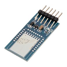
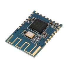
Product introduction:The JDY-10 transmission module is a bluetooth 4 protocol standard, the working band is 2. 4GHZ range, the modulation mode is GFSK, the maximum transmission power is 8dB, the maximum transmission distance is 50 meters. It has the characteristics of low power consumption, small size, strong signal, stable data transmission and so on. Product features: 1: supports the transmission of Android and IOS mobile phones.2: Supports one-to-many, many-to-one, many-to-many data transmission and control.3: Supporting network LED lamp (26 scenario mode, panel mode), brightness, white light, adjustable speed.4: Supports networking GPIO control (one-to-many, many-to-one, many-to-many).5: can be certified by FCC/CR and other standard.6: Supporting networked remote control (ultra-low power consumption), two dry batteries can be used for at least one year.7: support network 4 way PWM control.8: The maximum number of 8: networks is 255.9: supports broadcast and unicast MESH to send data.10: supports BLE master-slave operation without master-slave switching.11: at least 60% of the smart home application JDY-10M can be competent. Product application scope: 1: bluetooth networking LED lights (one to many, many to one, mobile phone or remote control, many to many control ).2: bluetooth network motor pulling applications (one to many, many to one, machine or remote control, many to many control).3: network panel switch, 86 switch (ultra-low power consumption).4: network smart home application (control, relays, curtains) control.5: networking sensor Application of network gateway of.6: Application of network gateway of WIFI.7: Application of Zigbeel network.8: Application of mobile phone network control. Technical specifications:
| Type | Specification parameter | |
| Working voltage | 1.9 – 3.6V | |
| Working temperature | -40 – 85℃ | |
| Maximum emission power | +8dbm | |
| Antenna | PCB board antenna | |
| Receiving sensitivity | -92dbm | |
| SMT welding temperature | <260 degree | |
| Communication interface | UART | |
| average current | Wake up the MESH mode | 28MA |
| Deep Sleep mode | 5 uA | |
Pin function description:
| Pin | Definition | Function | Description |
| 1 | RESET | Reset | Low level effective |
| 2 | E5 | 0UTPUT1 | The output pin can be controlled by networking, and the pin level has memory function. The next time you power up, you can keep the level set before. |
| 3 | H6 | 0UTPUT2 | The output pin can be controlled by networking, and the pin level has memory function. The next time you power up, you can keep the level set before. |
| 4 | E7 | 0UTPUT3 | The output pin can be controlled by networking, and the pin level has memory function. The next time you power up, you can keep the level set before. |
| 5 | F0 | 0UTPUT4 | The output pin can be controlled by networking, and the pin level has memory function. The next time you power up, you can keep the level set before. |
| 6 | F1 | K5 | Key 5 input pin (key target short address can be given special attention by AT instruction: K5 pin function for IO full open / full function pin, press – down to the network all modules OUT pin output low level, then press let all chess block output level in the network, in the application can be used for one key full open, one key full off and other functions application. |
| 7 | SWS | Download program pin | |
| 8 | VCC | Power Supply | |
| 9 | GND | Power supply | |
| 10 | PWM3 | PWM | AT+CLSSA0:This pin is a common PWM function |
| AT+CLSSB1:This pin is controlled by the white light pin of the LED lamp | |||
| U | STAT | Connection state pin | Unconnected low level, post connection high level |
| 12 | ALED | Broadcast instruction | MESH working instruction pin flashes once per second and outputs 100MS high level. |
| 13 | PWRC | Connect the AT instruction | Connection state: PWRC pin pull low, AT instruction PWRC pin pull up or suspend transmission.Unconnected state: PWRC pins can send AT instructions in any state. |
| 14 | RXD | Serial port input, level TTL level | |
| 15 | TXD | Serial output, level TTL level | |
| 16 | B0 | K1 | Key 1 input pin (short key address can be set by AT instruction). |
| 17 | B5 | K2 | Key 2 input pin (short key address can be set by AT instruction). |
| 18 | B6 | K3 | Key 3 input pin (short key address can be set by AT instruction). |
| 19 | PWMO | PWM | AT+CLSSA0:This pin is common PWM function AT+CLSSB1: this pin is LED lamp red light pin control. |
| 20 | Cl | K4 | Key 4 input pin (short key address can be set by AT instruction). |
| 21 | PWM1 | PWM | AT+CLSSA0: this pin is ordinary PWM function AT+CLSSBl: this pin is LED lamp blue light pin control.制 |
| 22 | PWM2 | PWM | AT+CLSSA0: this pin is ordinary PWM function AT+CLSSB1: this pin is LED lamp green light pin control. |
AT instruction set: The user can communicate through the serial port and the bluetooth chip. The serial port uses Tx, Rx two signal lines, and the baud rate supports 48009600, 19200.38400, 57600115200. The default baud rate of the serial port is 115200bps.Detailed description of the AT instruction set.(Note: the AT instruction must return to the line, the AT instruction can only take effect when the module is unconnected. Once the bluetooth module is connected to the mobile phone, the bluetooth module enters the data transmission mode) only for the feature UUID: FFEI, and MFSH can communicate with the instruction via the characteristic UUID: FFE2. Of course the serial port is connected to the state. You need to issue the AT command to send the AT instruction (including the MESH instruction) by pulling the PWRC pin low.(AT instruction is small and case sensitive, all in return, line end: rn, pay special attention to the computer serial tool hair terminator, do not need to input rn, only need to check the send back to the line. Inquiry – version number:
| Instruction | Response | Parameter |
| AT+VER | + | Param:EditionDefault: +JDY-10M-V2.1-MESH |
Check – bluetooth MAC address:
| Instruction | Response | Parameter |
| AT+MAC | +MAC: | Param: MAC address |
Reset – soft reset:
| Instruction | Response | Parameter |
| AT+RESET | +OK |
Set / query – bluetooth name:
| Instruction | Response | Parameter |
| AT+NAME | +0K | Param: bluetooth nameDefault name: the longest 18 bytes of JDY-10M |
Set / query – serial port baud rate:
| Instruction | Response | Parameter |
| AT+BAUD | 0K | Param: <0-7)0:115200bps1:57600bps2:38400bps3:19200bps4:9600bps5:1800bps默认值:0 |
| AT+BAUD | +BAUD): |
Setup / check – device type:
| Instruction | Response | Parameter |
| AT+CLSS | +OK | Param: (00-FF)A0: through mode (support 1 stroke, key switch input, OUT output)Bl: LED lamp mode (support LED lamp, keystroke input, OUT output)C0: low power remote control (only supporting key input) Default: A0 transmission mode |
| AT+CLSS | +CLSS= |
Set off – disconnect connection:
| Instruction | Response | Parameter |
| AT+DISC | +0K |
Set up / query – Networking ID:
| Instruction | Response | Parameter |
| AT+NETID | +0K | Param: (12 bytes) default: 123456789ABC |
| AT+NETID | +NETID= |
Set / query – short address of networking:
| Instruction | Response | Parameter |
| AT+MADDR | OK | Param (2 bytes)Default: one bit after MAC address (HEX) |
| AT+MADDR | +HADDR= |
Setting / checking the -APP connection password:
| Instruction | Response | Parameter |
| AT+PSS | +0K | param: (2 bytes) Default:12345 |
| AT+PSS | +PSS= |
Set / check a APP cipher connection switch:
| Instruction | Response | Parameter |
| AT + ISCEN | OK | Param: (1 bytes)1: hit the APP password switch0: APP connections do not require a password Default: 0 |
| AT+ISCEN | +ISCEN= |
Set / check – the short address of the key switch:
| Instruction | Response | Parameter |
| AT+KVALUE | +0K | Param: (4 bytes)01FF: indicates that K1 is configured as a broadcast mode. When K1 is pressed, all devices will receive K1 key values.0108: means that K1 is set to unicast. When K1 is pressed, only the device’s short address is 08 of the device receiving the K1 key.02FF: means that K2 is set to broadcast mode. When K2 is pressed, all devices will receive K2 key value.0208: means that K2 is set to unicast. When K1 is pressed, only the device’s short address is 08 of the device receiving the K2 key.03FF: indicates that K3 is configured as a broadcast mode. When K3 is pressed, all devices will receive K3 key values.0308: means that K3 is set to unicast. When K3 is pressed, only the device’s short address is 08 of the device receiving the K3 key.04FF: means that K4 is set to broadcast mode. When K4 is pressed, all devices will receive K4 key value.0408: means that K4 is set to unicast. When K4 is pressed, only the device’s short address is 08 of the device receiving the K4 key.05FF: means that K5 is set to broadcast mode. When K5 is pressed, all devices will receive K5 key value.0508: means that K5 is set to unicast. When K5 is pressed, only the device’s short address is 08 of the device receiving the K5 key. |
| AT+KVALUE | +KVALUE= | Param2: (2 bytes)01: means to read the address of the K102: means to read the address of the K203: reads the tore of K304: means to read the address of the K405: farmer reads K5’s address |
The number of serial ports MKSH is transmitted :(one to many, many to one, many to many)
| instructions | Target short circuit address | Data |
| AAFC | 2byte | Param |
Serial MKSH data receiving:
| instructions | Target short circuit address | Data long | Data |
| AA | lByte | lByte | lOByte |
| BB | lByte | lByte | lOByte |
Serial port MESH function data: (one to many, many to one, many to many)
| instructions | Target short circuit address | Data |
| AAFC | 2byte | Param |
I0 MESH Level control:
| IOPort number | Param | Function | Data format |
| OUT1 | E7F101 | OUT1 Pin high level | HEX |
| E7F100 | OUT1 Pin low level | HEX | |
| OUT2 | E7F201 | OUT2 Pin high level | HEX |
| E7F200 | OUT2 Pin low level | HEX | |
| OUT3 | E7F301 | OUT3 Pin high level | HEX |
| E7F300 | OUT3 Pin low level | HEX | |
| OUT4 | E7F401 | OUT4 Pin high level | HEX |
| E7F400 | OUT4 Pin low level | HEX | |
| ALL | E7FFFF | OUT All for high level | HEX |
| E7FOOO | OUT All for low level | HEX |
Package included:1 x JDY-10M 4 bluetooth Module Master-Slave Support MESH Networking App Transmission
Reviews
There are no reviews yet.